In the early days of mini-z, people would use modified motor, and every now and then, a board would burn up. People threw away the board and got a new one. It was Phil Ng from PN Racing before there was PN Racing that decided to investigate how to fix the board. There was a big pile of boards. He noticed there was burnt spots on the FET. Tried replacing it, and saw that it worked again. From there, he started replacing FETs for racers at the local track in Hong Kong. Then he had an idea of stacking two FETs on top of each other. Sure enough, car went faster. Then he looked for all the possible FETs that fit, tried each one, and found the ones that gave the best performance. That is how the PN Aberrant FETs came about.
Soon, word spread, and everyone are doing FET modification and FET stacking.
Operation
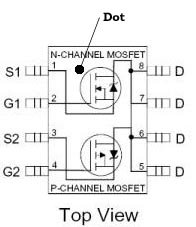
The mini-z use a surface mount MOSFET or FETs in a SO-8 packaging. Two identical fets are needed to control the motor. Each fet chip contains a N-channel and a P-channel switch. The reason for both N channel and P channel is because a MOSFET works differently than a contact switch. For a MOSFET, you have to decide whether to put it in front of the motor or after the motor. You will use a different FET for each case. If you want to put a switch in front of the motor (positive side), you need a P-channel (PNP) MOSFET. Use a N-channel (NPN) MOSFET for the negative side of the motor. (Easy way to remember is P for positive, so is on positive side. N is negative, so is on negative side.)
Each MOSFIT contains three connections: gate, source and drain.
The gate as the name implies controls the switch.
Current flows from drain to source for NPN, and source to drain for PNP.
(Way to remember it as negative personality drains your energy while positive
personality is a source for energy.)
For a NPN MOSFET positive voltage on the gate turns on the switch. No voltage
turns it off.
PNP MOSFET is the opposite. Apply voltage at the gate to turn it off. The MOSFET
is normally turn on.
(Way to remember it is ask yourself if is normally turned on or not. N in
NPN for Negative, so is normally off. P in PNP for Positive, so is normally
on.)
To get no voltage, the circuit board use a pull down resistor to connect the
gate to the ground. If you just leave the connection floating, sometimes static
current can accidentally turn on the MOSFET.
The reason for having two chips each with a p and n channel FET is so the car can go in reverse. A pair of p and n channels FET turns on at the same time to give forward speed. The other pair of n and p FET will turn on for reverse. Presumably, the computer on the car turns on one set of FET or the other. If both gets turned on at the same time then there would be a short.
Question is what does a NPN FET have to be after the motor, or why PNP have to be before the motor. Reason is that for the NPN FET, as soon as it is turned on, the drain and source will be at negative voltage once is turned on. If the NPN FET is accidentally placed before the motor, then source will be at battery voltage. The gate voltage always have to be higher than the source for the FET to turn on. Since the gate gets its voltage from the microcontroller, and there is some voltage drop in the microcontroller. Therefore, the FET will not get enough voltage to turned on.
PNP FET has to be in front of the motor for similar reason, but logic is flipped around. When the PNP FET is in front of the motor, the source will be at battery voltage. If the gate is connected to ground, then the FET is turned on because gate has to be at lower voltage than source to work. The more the gate is lower than the source, the more the FET is turned on and less resistance. If the PNP FET is accidentally connected to the back of the motor, then the source will be at ground voltage. If the gate is also at ground voltage then the FET is permanently off. The only way to turn it on is if you have voltage that is more negative than ground. You will need to connect extra batteries to the negative side of the last battery to get more negative voltage than ground.
 Note: Dot on chip
is on the right side on both chips.
Note: Dot on chip
is on the right side on both chips.
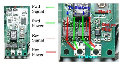
Picture of board shows flow of power thru the MOSFET chip on the mini-z board. Signal wire instructs each of the two individual MOSFETs on the chip to turn on. The power wire connects to the battery. By turning on the the right P and N channel MOSFET on the chip, the car can go forwar or reverse.
Performance
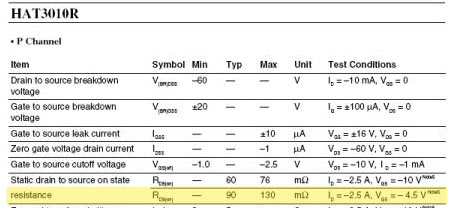
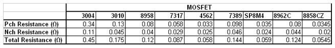
Above is from the data sheet for the 3010 mosfet that is used on the latest mini-z. Kyosho claims it is 30% faster than the old 3004 mosfet. The important parameter to watch for is the on state resistance. It gives the resistance at two voltages, 4.5V and 10V. Ignore the negative sign on the voltage. It just tells you this is used on the positive side of the motor. The max resistance is 130 mOhms or .13 Ohms. Remember, this is only for the P channel as stated in the upper left hand corner of the sheet. Another page in the data sheet shows the N channel resistance to be .045 Ohms. Since both P and N channel runs the motor, you have to add up the resistance which comes out to be .175 Ohms.
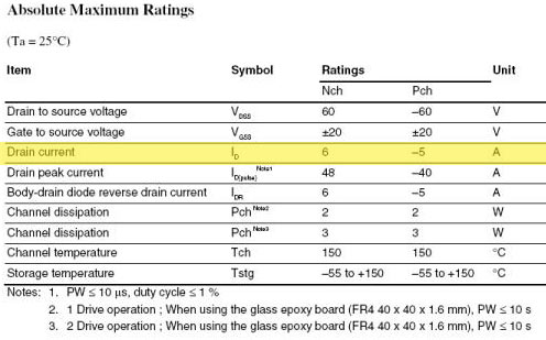
The maximum continuous current is show also in the data sheet under "Drain
current". P channel is 5 amps and N channel is 6 amps. You have to take
the lower of the two since that is the limiting factor. However, remember that
the current numbers are not realistic in that heat is what really kills the
mosfet. Remember power through any electronic device is I^2*R. I is current
and R is resistance. That is the power that the mosfet has to dissipate and
stay cool enough to have a long life. It comes back to having a lower resistance
allow you to run higher current doesn't matter what the spec say.
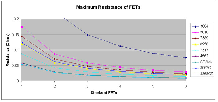
As seen in the above chart, 4562, SP8M4 and 8858CZ are the best MOSFET available. The 8858CZ made by Fairchild is the best by a small margin. One of that is equivalent to at least a stack of 6 stock 3004 or stack of 4 3010 found in the latest upgraded mini-z chassis. Note that the chart above does not include the PNRacing AN0113 MOSFET since there is no information available for that. Some people claim it is better than 4562.
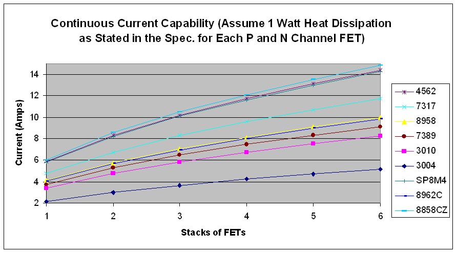
Here is the estimated real continuous current rating of the FETs without heatsink. The 4562 was the old favorite. However, it is no longer available. The SP8M4 and 8858CZ are the new replacement. That is not a problem since the 8858CZ is the best of them all base on manufacture data. One stack of 8858CZ can handle 6 amps of current continuous. Given that during acceleration, stock mini-z runs at about 3 amps. Modified maybe 4 or 5, the 8858CZ is enough. Two would be good for added safety. A stack of 3 8858CZ can handle 10 amps continuous. That is enough power to melt the motor! Of course, the other reason to stack FETs is for low resistance.
8858CZ is the best choice.
Stacking FETs
The graph shown above has a maximum of 6 FETs stacked together. In practice, 3 is the practical maximum. There are reports that after a stack of 3 FETs, operation becomes eratic. There may be two reasons why. The gate on a FET acts like a capacitor. The analogy is the gate being a cup. It takes some electricity to fill the cup before the FET turns on. If you have 6 FETs, then you have to fill 6 cups with electricity before all 6 FETs turn on. The FET driver on the board may not be able to supply that much current fast enough to turn on the FETs at the switching frequency of the speed control. Therefore, the FETs never turn on fully. In this scenario, at maximum throttle, there would be no issue since the FET is turned on full time. Second possible reason is resonance in the FET gate circuit. Since each FET acts like a capacitor, and the wires leading up the FET acts like an inductor, some resonance may be set up which cause the FETs to turn on and off by themselves at very high speed. When you parallel FETs, the right way to do it is to tie a resistor from the FET driver to each FET. In practice, there is rarely a need to stack more than 3 FETs, and nobody use a resistor to connect to each FET. There seens not be a proble with less than 3 FETs.
How to Install FETs - Soldering Techniques
Reference:
Continuous power dissipation of typical SO-8 packaging is 1 watt. Base on Fairchild application note 1032. For conservative continuous running, divide the above current chart by 2.
MOSFET heat dissipation calculation.
Data Sheets:
International Rectifier - IRF7389
Fairchild Semiconductor - FDS8958