Not sure what mini-z parts are compatible with another, here is a handy reference:
Mini-z Parts Compatibility List
It is found in the Kyosho site: http://web.archive.org/web/20080122182509/http://www.kyosho.com/jpn/support/option/pdf/mini-z_racer_060322-e.pdf
Must Do Upgrades
1. The very first upgrade should either be tires or the pinion gear. Do not use the stock pinion gear. The reason is that the stock gear is actually incompatible with the stock differential. That is right, Kyosho made a mistake, and made the stock pinon that came with the kit incompatible with its own differential. What to do: Buy the PN Pro Match pinion. At less than $3, is not going to break the bank. Tires comes next. use 25 degree in front and 6 or 8 in the rear.
2.Carbon fiber T-plate and front springs. This will let you dial in the handling.
3. Disk damper - Must have to prevent chatter during cornering. Chattering is due to wheel hop that can be solved with disk damper.
4. Motor mount and ball diff or gear diff. I like the gear diff since is less maintenance and is very smooth. Motor mount allow for fine adjustment of gear mesh as well as cools the motor.
5. FET mod. People think FET mod is for the extreme speed demon. Actually,
to be competitive in stock or modified, you need a FET mod. Even with the four
FETs on the MR03 board, the resistance is still high. The 3010 FETs are relatively
low performance. Recommendation is to at least change them out to 4562, 8858
or the PN FETs. Even better is to stack the bottom FETs so you have a total
of 6 FETs. You can definitely feel the difference as well as see the longer
run time with more punch. If you are racing, FET mod is a must to be in the
game.
Pot Cleaning
Pot cleaning should be part of normal maintenance.
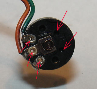
The problem with the mini-z pot is that it only use 2 wires instead of 3 wires in a normal servo. 3 wire pot creates a voltage divider circuit. The two wires at both ends of the pot are the reference voltage, and the middle wire sense the voltage. With the voltage divider configuration, the pot is not sensitive to variation in resistance. The mini-z circuit use only two wires which use the pot as a variable resistor. The variable resistor forms part of a RC circuit for the steering microcontroller on the board. The purpose of the 2 wire pot is to cut cost. It eliminates the need for an AD converter that is required to sense voltage in a normal 3 wire voltage divider circuit. The disadvantage with the 2 wire pot configuration, is that it is very sensitive to change in resistance. Fine track dust that gets into the pot adds resistance between the pot arm and the resistance element. It is intersting to note that the upgraded AD band board for mini-z use a 3 wire pot.
The solution to the pot issue is to keep it clean. Use electrical cleaner to clean the pot. DeoxIT works well to clean it followed by DeoxIT Gold for contact protector. To make cleaning last longer, seal up the openings in the pot with some sealant. With the vibration in the car, the fine dust that get into the chassis will get into any small opening.
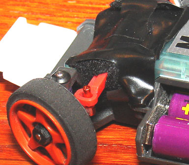
On 3 occasions, debris got into the steering servo and caused the gears to jam. Debris also contaminates the pot. Here is a test solution. I used a piece of felt to seal up the opening between the steering rack and body, and taped it down with electrical tape. Looks ugly, but if it works... Lately, I have just unscrew the 4 screws on the cover and lift the cover a little to blow out the dust with a air can.
Power Connection
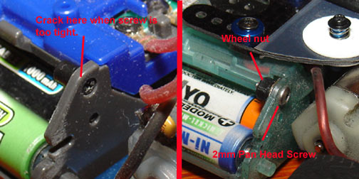
With stock motor, the power connection works fine. However, with modified motors, lots of current are flowing thru the battery connection. Two things wrong with the stock connection. The stock screw cannot be tightened too much. Otherwise, the chassis would crack because of the small head size of the screw. If the screw is not tight enough, there would be high resistance in that connection especially if there are some corrosion in the joint. High resitance cause lots of heatbuild that further soften the plastic nut causing the screw to loosen further. Sometimes it leads to intemitten loss of power. Car would be running fine one moment, and the next stops completely. Way to fix it is to use a M2 pan head screw. Can be bought from PN racing. Use a wheel nut and the screw to clamp the power connection. For even better clamping, use a allow wheel nut and a washer under the head of the panhead screw (not shown). You can tighten it hard, and have a very good connection then. Remember, same thing with the motor connection. Check the tightness of it regularly. Sometimes it can get loose and cause high resistance.
Battery Cleaning
The contacts on the battery are nickel plated. Over time, a layer of oxidation develops on the battery. The result is high resistance between the battery and the contacts on the chassis. Typically, with install and removal of the battery, the scraping action of the contacts cleans the oxidation off. However, that may not be enough. On an AD band car, the circuit board seems to be very sensitive to power loss. The board shuts down when there is not good enough of a contact on the battery. The best way to clean the battery contact is to use a fine emery paper. You don't want to sand the nickel plating off, just remove the oxidation layer.
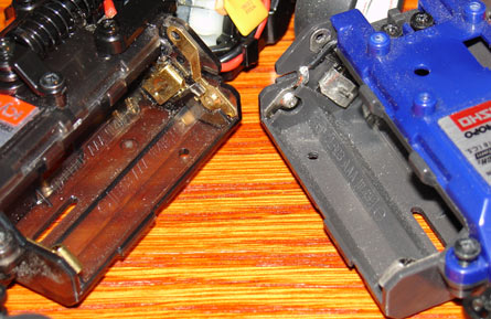
On a regular chassis, the battery contacts are nickel plated, so the hard nickel
scrapes oxidation off the battery to some degree. On the fancy SP skeleton chassis
(MZF203GM) with gold plated contacts, the gold is soft, so is not as effective
in scraping the oxidation off of the battery. In that case, it is more important
to keep the oxidation off of the battery with emery paper.
Gold Chassis
The normal chassis (MZ201B) has nickel plated battery contacts. The upgrade chassis (MZF203GM) which cost around $5-$10 more has glod plated battery contacts. The gold contacts looks really trick, but the question is whether they actually do any good. I decided to run a test with the ICE charger. A set of Duracell 1000 mah batteries were place in both chassis and hooked up to the ICE charger to discharge at 3 Amps. The ICE charger gives you the voltage of the battery during discharge. The batteries were placed in the gold chassis, back in the normal chassis, back in the gold chassis and back in the normal chassis again. For the voltage reading, since the volts is dropping constantly, a wait of about 5 seconds is used before voltage measurement is taken. The results is that in the gold chassis, the voltage reading was 4.1. In the normal chassis, the voltage reading was 4.0V. Therefore, there is a 2.5% improvement for the gold chassis. Realize neither the gold or the normal chassis is perfect. Using a volt meter to measure voltage drop between the battery and the contacts, there is around .05V drop between the the end of the one battery and beginning of the next. This is at 3 Amps, so at 6 Amps, there would be double the voltage drop. Since there are 4 batteries, you can have .2V drop total. Soldering the batteries together will probably make the voltage drop better. Realize that in modified class, the voltage drop is not significant since there is already plenty of power. In stock class, lower voltage drop might give you more of an edge.
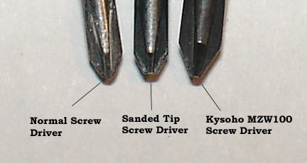
Screw Driver
The typical miniture screwdrivers does not work very well on mini-z screws. The tip of the driver is quite sharp, while the screw head on the mini-z has a truncated bottom. As a result the sharp end of the screw driver hits the shortened bottom of the screw and doesn't get a full engagement. It makes it very easy to strip a screw. Several ways to solve this. You can get a special screwdriver set from rckennon part# 700610. You even get a tweezer with that. You can get the MZW100 screw driver set from Kyosho. That is pretty expensive at $28. Or, you can moldify a Radio Shack or other similar miniature screwdriver by sanding the sharp tip off. You can use a file too, but sand paper will do fine and gives a better finish. RJR Cool Tools also has some JIS standard screw drivers that fits Mini-Z screws.
Bumpers
Mini-Z cars don't have bumpers. Their plastic bodies can take quite a beating and not crack. However, even on RCP tracks, a right hit can crack the body. The ones with the lights close to the front of the body is more vulnerable since the lights are made from transparent plastics which are brittle. After completely destroying one body and in another day, I cracked two bodies, I decided to find a solution. Cutting a bumper from a flat sheet of plastic and bolting it on using the bottom holes on the chassis works ok. Problem with a flat bumper is when it hits the railing on the RCP track, it digs in, and the car comes to a complete stop. It gouge the track railing and put a lot of stress on the chassis. I found a much better solution using coffee can lids. The lid on a can has may properties that are perfectly suited for use as a bumper. It is very soft and retains its shape even after major crashes. The softness means it absorbs the impact. As a added bonus, there is a vertical lip to the edge of the lip so the bumper does not gouge into the RCP track. After cutting to shape, I used some X-Mod screws to install the bumper on the chassis. Mini-z screws would require some washers since they are pretty long.
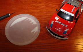 Find a lid with the right
diameter to match the car body.
Find a lid with the right
diameter to match the car body.

Find the right diameter, and the shape of the lid can match the body quite well. Note lid drops down the clear the bottom of the body then goes vertical to a good impact surface. Fits like a glove and works well.
Body Prep
Usually, after getting a new body, the first thing I do is to use a super heavy super glue to glue down the mirrors. Use thin super glue to glue down the windshield wipers. Use the kind of super glue that are meant for plastics. Regular superglue will fog up the windshield. Use the same glue to place a bead around the front headlight. Finally, check steering wheels at full lock for clearance to the body. Also, use the thick super glue to reinforce the front light back cluster.