Track Timer
Want to know how fast you are, or if an improvement really result in faster time? If money is no object and you can find one for sale, by all means get the CORE timing system. However, if you have a computer laying around, you can build a laser track timer for under $20 or almost free since most people already have the needed parts laying around. The instructions here only describe a 1 car system. Multiple car system are similar. The only difference would be that several laser are needed stacked vertically at different heights. Each car would have a flag on the antenna set at the height of its laser beam to only trigger one laser. 1 car laser system is easier to set up and build with minimal hardware. That is the one I have. You just attach the laser to the track rail.
Finally, here is the most useful site that describes all about timing systems: http://www.cenobyte.nl/slotracemanager/hoofdframe.html
Easy lap counter that use camera instead of sensors http://sites.google.com/site/easylapcounter/
If you want a professional lap timer software, go to GiroZ Lap timer http://www.giro-z.com/
Here is the latest version of GiroZ lap timer software at RC Kenon for download. It comes with a track designer. You put in your track layout on the track designer, and the most likely car path. In the timmer program, it will replay with cars going around the track you designed for a graphical representation of the race. Best of all, the Giro Z timer works not only with the Giro Z system, but any home made timing system as well. There is no charge for download. http://www.rckenon.com/public_html/shop2/catalog/index.php
Here is the step by step direction.
Material:
Radio Shack NPN Silicon Infrared Phototransistor #276-145
Laser from ebay etc.
Parallel printer port cable
200 - 1,000 ohms resistor
Step 1:
Download the free track timer program here: http://www.gregorybraun.com/LapTimer.html
Also, download the "PARPORT" parallel port detection program here: http://www.cenobyte.nl/slotracemanager/hoofdframe.html It helps greatly to trouble shoot your circuit when you can see the computer register your parallel port.
Step 2:
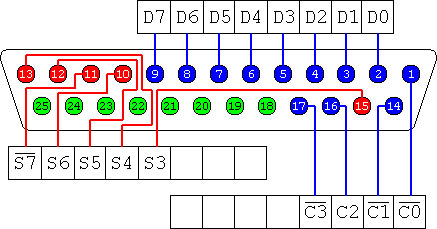
Build the harness. Connect pin# 10 of the parallel port to the "Collector" or the short leg of the phototransistor. Connect the "Emitter" or the long leg of the phototransistor to the 200-1,000 ohms resistor. Connect the resistor to pin# 25 of the parallel port. The resistor should be in series with the phototransistor. It is very important to have the resistor in place so that when the phototransistor turns on, you are not shorting the parallel port which can destroy the port - bad.
Here is the pin out of the parallel port. Remember, here you are looking straight at the end of the male connector of the parallel port.
Step 3:
Wrap some tape around the phototransistor exposing only the lens end of it so ambient room light will not affect it. Aim a laser light at it from across the track. When the car pass by, it should interrupt the laser beam, and activate the lap timer.
Step 4:
Start the software, and run the race. Some configuration hints this is what worked for me. Some options may be different depending on computer. Under options-ports, use "Printer" port with "LTP3: 0x03BC" selected. Check the "TrakMate Sensor Compatibility" box. Leave the "Track Power Relay Installed" unchecked. Under options-settings, uncheck the "Invert Lap Switching Logic" box.
